micromagnetic_FF_3D
Field-dependent magnetic microstructure around imperfections in bulk ferromagnets
Parameter |
Description |
Units |
Default value |
|---|---|---|---|
scale |
Scale factor or Volume fraction |
None |
1 |
background |
Source background |
cm-1 |
0.001 |
radius |
Structural radius of the core |
Å |
50 |
thickness |
Structural thickness of shell |
Å |
40 |
nuc_sld_core |
Core scattering length density |
10-6Å-2 |
1 |
nuc_sld_shell |
Scattering length density of shell |
10-6Å-2 |
1.7 |
nuc_sld_solvent |
Solvent scattering length density |
10-6Å-2 |
6.4 |
mag_sld_core |
Magnetic scattering length density of core |
10-6Å-2 |
1 |
mag_sld_shell |
Magnetic scattering length density of shell |
10-6Å-2 |
1.7 |
mag_sld_solvent |
Magnetic scattering length density of solvent |
10-6Å-2 |
3 |
hk_sld_core |
Anisotropy field of defect |
10-6Å-2 |
1 |
Hi |
Effective field inside the material |
T |
2 |
Ms |
Volume averaged saturation magnetisation |
T |
1 |
A |
Average exchange stiffness constant |
pJ/m |
10 |
D |
Average DMI constant |
mJ/m^2 |
0 |
up_i |
Polarisation incoming beam |
None |
0.5 |
up_f |
Polarisation outgoing beam |
None |
0.5 |
alpha |
Inclination of field to neutron beam |
None |
90 |
beta |
Rotation of field around neutron beam |
None |
0 |
The returned value is scaled to units of cm-1 sr-1, absolute scale.
Definition This model is a micromagnetic approach to analyse the SANS that arises from nanoscale variations in the magnitude and orientation of the magnetization in bulk ferromagnets in the approach to magnetic saturation (single domain state). Typical materials are cold-worked elemental magnets, hard and soft magnetic nanocomposites, amorphous alloys and precipitates in magnetic steel [5]. The magnetic SANS depends on the magnetic interactions, the magnetic microstructure (defect/particle size, magnetocrystalline anisotropy, saturation magnetisation) and on the applied magnetic field. As shown in [6] near magnetic saturation the scattering cross-section can be evaluated by means of micromagnetic theory
with the field-independent nuclear and magnetic SANS cross section (due to nanoscale spatial variations of the magnetisation).
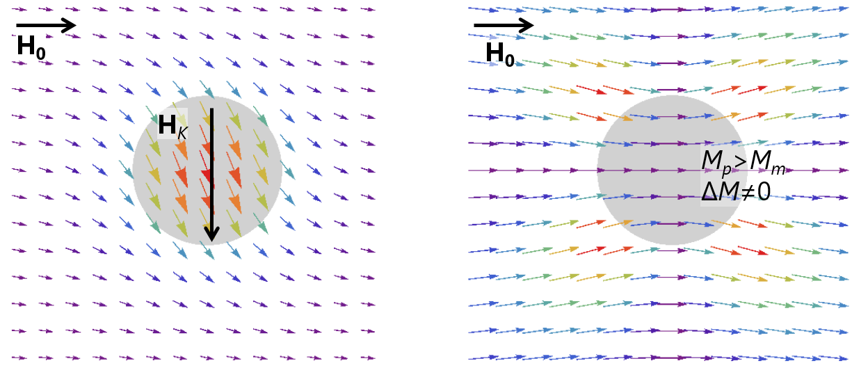
with Hi the internal field, i.e. the external magnetic field corrected for demagnetizing effects and the influence of the magnetodipolar field and of the magnetic anisotropy [3]. This magnetic field dependence of the scattering reflects the increasing magnetisation misalignment with decreasing externally applied magnetic field with a contribution SK×RK due to perturbations around magnetic anisotropy fields and a term SM×RM related to magnetostatic fields. The magnetic moments decorate perturbations in the microstructure (precipitates, grain boundaries etc). The anisotropy-field function SK depends on the Fourier transform of the magnetic anisotropy distribution (strength and orientation) in the material, and the scattering function of the longitudinal magnetisation SM reflects the variations of the saturation magnetisation, e.g. jumps at the particle-matrix interface. RK and RM denote the micromagnetic response functions that describe the magnetisation distribution around a perturbation in magnetic anisotropy and flucutations in the saturation magnetisation value.

Fig. 83 Magnetisation distribution around (left) a particle with magnetic easy axis in the vertical direction and (right) a precipitation with a magnetisation that is higher than the matrix phase.
The micromagnetic response functions depend on magnetic material parameters MS: average saturation magnetisation of the material, Hi: the internal magnetic field, A the average exchange-stiffness constant. In the vicinity of lattice imperfection in ferromagnetic materials, antisymmetric Dzyaloshinskii–Moriya interaction (DMI) can occur due to the local structural inversion symmetry breaking [1]. DMI with strength D can give rise to nonuniform spin textures resulting in a polarization-dependent asymmetric scattering term for polycrystalline ferromagnetic with a centrosymmetric crystal structure [6]. We assume (for simplicity) an isotropic microstructure (for SM) and random orientation of magnetic easy axes (additionally for SK) such that the contributions of the magnetic microstructure only depend on the magnitude of q. Considerations for a microstructure with a prefered orientation (texture) can be found in [2]. In the code the averaging procedure over the random anisotropy is explicitely performed. A specific orientation distribution can be implemented by rewriting the model.
The magnetic field is oriented with an inclination of α to the neutron beam and rotated by β. The model for the nuclear scattering amplitude, saturation magnetisation is based on spherical particles with a core shell structure. For simplicity, only the core has an effective anisotropy, that is varying randomly in direction from particle to particle. The effect of different, more complex spatial profiles of the anisotropy can be seen in [4]. The magnetic scattering length density (SLD) is defined as ρmag=bHMS, where bH=2.91∗108A−1m−1 and MS is the saturation magnetisation (in A/m).
The fraction of “upward” neutrons before (‘up_frac_i’) and after the sample (‘up_frac_f’) must range between 0 to 1, with 0.5 denoting an unpolarised beam. Note that a fit may result in a negative magnetic SLD, and hence magnetisation, when the polarisation state is inverted, i.e. if you have analysed for a I00 state wheras your data are I11. The model allows to construct the 4 spin-resolved cross sections (non-spin-flip I00, I11 and spin-flip, here I01=I10), half-polarised SANS (SANSpol, incoming polarised beam I0 and I1, no analysis after sample ‘up_frac_f’$=0.5$), and unpolarised beam (‘up_frac_i’$=$’up_frac_f’$=0.5$). Differences and other combinations between polarised scattering cross section, e.g. to obtain the nuclear-magnetic interference scattering, or subtraction of the residual scattering of the high field reference state can be constructed with a custom model (Fitting> Add/Multiply Model) and using approbriate scales. For dense systems, special care has to be taken as the nculear structure factor (arrangement of particles) does not need to be identical with the magnetic microstructure e.g. local textures and correlations between easy axes (see [7] for further details). The use of structure model is therefore strongly discouraged. Better Inuc, SK and SM are fit independent from each other in a model-free way.

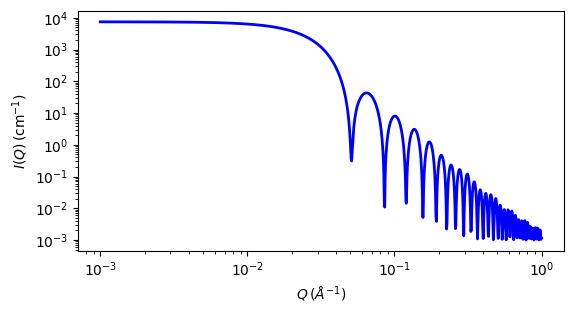
Fig. 84 1D plot corresponding to the default parameters of the model.
Source
micromagnetic_FF_3D.py
⋆ micromagnetic_FF_3D.c
⋆ magnetic_functions.c
⋆ gauss76.c
⋆ core_shell.c
⋆ sas_3j1x_x.c
References
Authorship and Verification
Author: Dirk Honecker Date: January 14, 2021
Last Modified by: Dirk Honecker Date: September 23, 2024
Last Reviewed by: